angle to the vertical. The motion of the cart causes the pendulum to oscillate as well. In the following diagram, the cart moves to the left with the pendulum following because of the cart’s inertia: In figure 1, a pendulum of mass and length is attached to a cart of mass which is constrained to move in one direction.
Feb 03, 2018 · Yes it is friction works most of the time opposite to the direction of Motion but not always in this situation when the truck is accelerating in forward direction there will be tendency of motion between the truck and the block and so since there is tendency of motion between them so the block will exert a friction force on the block in the left direction which will oppose the motion of truck
B. Velocity contains information about the direction of motion while speed does not. Jane walks to the right at a constant rate, moving 3 m in 3 s.
11. A ball of mass 1.5 kg is moving in a circular path of radius r figure with a speed of 8 m/s. 10 m as shown in the (a) (b) (c) (d) Please state which force keeps the ball in circular orbit Show all the forces acting on the ball along the direction. Show all the forces acting on the ball along the g direction. From part (b) and (c) find the
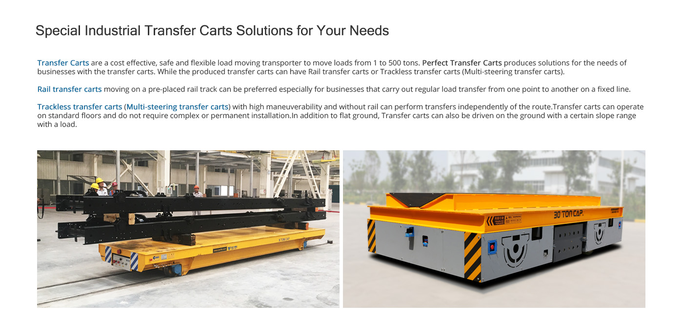
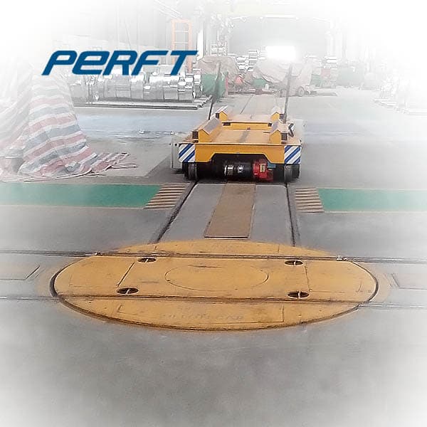
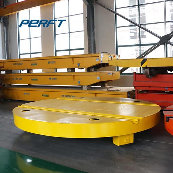
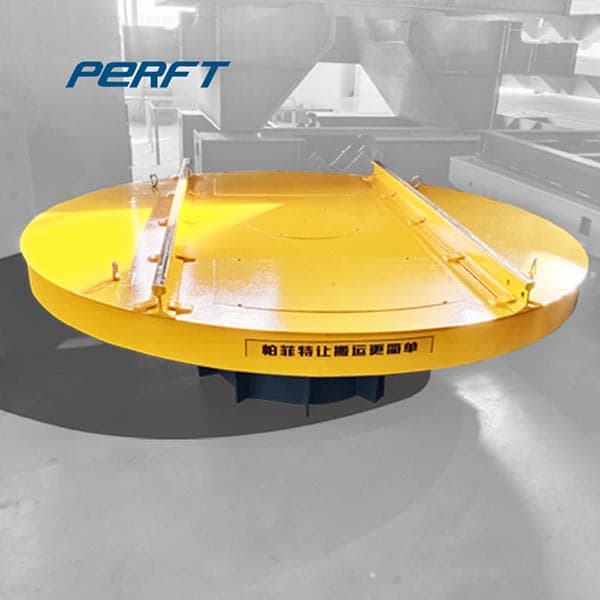
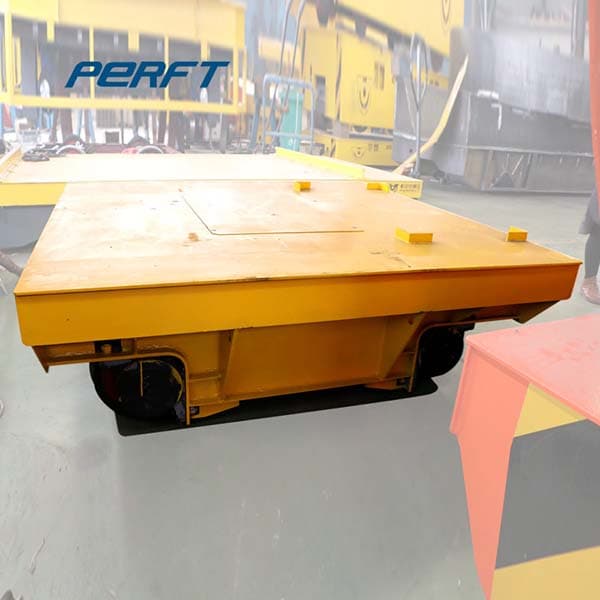
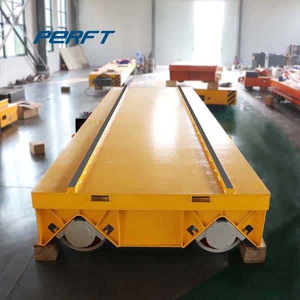
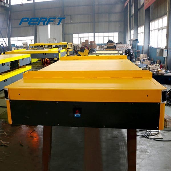
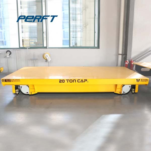
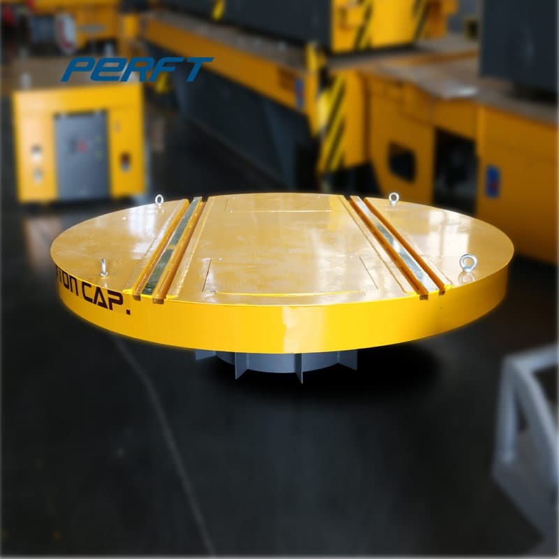
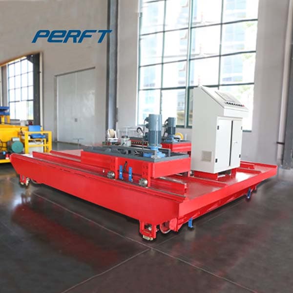
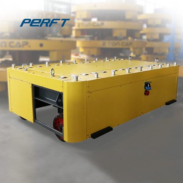
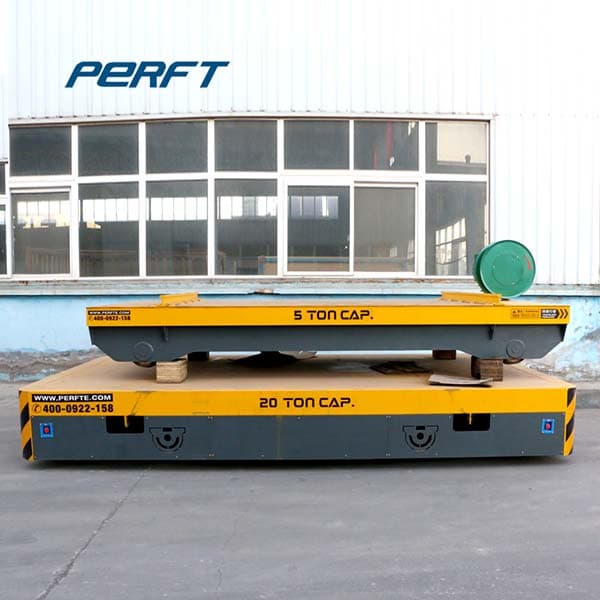
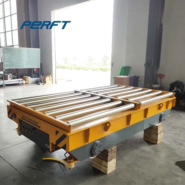
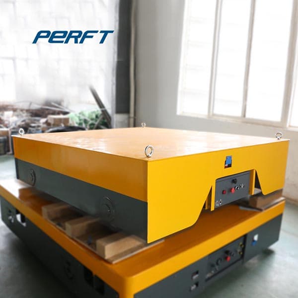
Transfer cart is a kind of cost-effective, safe and flexible material handling cart widely used in fabrication shops, warehouses, metallurgical plants, etc. for load transportation. It can also cooperate with overhead and gantry cranes in the workshop to transport heavy loads across the bridge.
A motorized cart for lifting and transporting a drum. The cart includes a frame defining at its forward end a rearward-extending frame recess for receiving a drum, a feature for engaging the lower end of a drum and supporting the drum within the frame recess, another feature for engaging an upper end of the drum when received in the frame recess, first wheels at the lower extent of the frame
approximations involved, the basic finite control volume analysis performed with a paper and pencil has always been an indispensable tool for engineers. In Chap. 5, the control volume mass and energy analysis of fluid flow systems was presented. In this chapter, we present the finite control volume momentum analysis of fluid flow problems.
across a surface. This is a force that opposes the motion and points in the opposite direction from the velocity. Static friction denoted by the symbol f s, is a force that keeps an object at rest stuck to a surface and prevents its motion. It points in the direction that prevents motion. Typically, it isPerfectr than the kinetic friction that
direction of (a G) n and (a G) t. 2. Draw a free body diagram accounting for all external forces and couples. Show the resulting inertia forces and couple (typically on a separate kinetic diagram). 3. Compute the mass moment of inertia I G or I O. 5. Use kines if there are more than three unknowns (since the equations of motion allow for
Kinetic energy is a scalar (it has magnitude but no direction); it is always a positive number; and it has SI units of kg · m2/s2. This new combination of the basic SI units is known as the joule: 1joule = 1J = 1 kg·m2 s2 (6.2) As we will see, the joule is also the unit of work W and potential energy U. Other energy units often seen are: 1erg
the motion of the center of mass is related to P by: vCM = P M and aCM = 1 M dP dt 7.1.6 The Motion of a System of Particles A system of many particles (or an extended object) in general has a motion for which the description is very complicated, but it is possible to make a simple statement about the motion of its center of mass.
direction of motion as shown. How much work will be done in pulling this barge a distance of 3.0 kilometers? Ans. The component of the force along the direction of motion is F x = T cos F x = 14,000 N cos 18 = 13,314.79 N Since there are two such cables, the total force along the x-direction is F x = 13,314.79 N 2 = 26,629.58 N
The problem is therefore one-dimensional along the horizontal direction. As noted, f opposes the motion and is thus in the opposite direction of F floor. Note that we do not include the forces F prof or F cart because these are internal forces, and we do not include F foot because it acts on the floor, not on the system. There are no other
AB and rests on a moving belt. Knowing that m s = 0.25 and m k = 0.20, determine the magnitude of the horizontal force P that should be applied to the belt to maintain its motion (a) to the right, (b) to the left. SOLUTION We note that link
Since the barge is flat bottomed, we can assume that the drag force is in the direction opposite of motion of the barge.) Figure 6.4 (a) A view from above of two tugboats pushing on a barge. (b) The free-body diagram for the ship contains only forces acting in the plane of the water.